What is a DXF?
DXF stands for Drawing Exchange Format. It's a common file format that allows different Computer-Aided Design (CAD) programmes to share drawings.
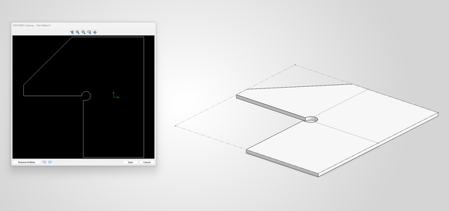
For our purposes, think of it as a full-size digital template of the part you want cut. It shows the outside edges, holes and slots, just like a paper template would.
The cutting company loads this file into its software, which then uses the outlines to prepare the cutting programme for its CNC plasma or laser cutter.
One thing worth knowing is that a DXF doesn't normally tell the cutting company what material you want. You'll still need to specify things like steel grade, thickness and how many parts you need.
Why is it useful to you?
If you've got a complicated bracket to make, or need several of the same part, getting them CNC cut can save a fair bit of time and effort.
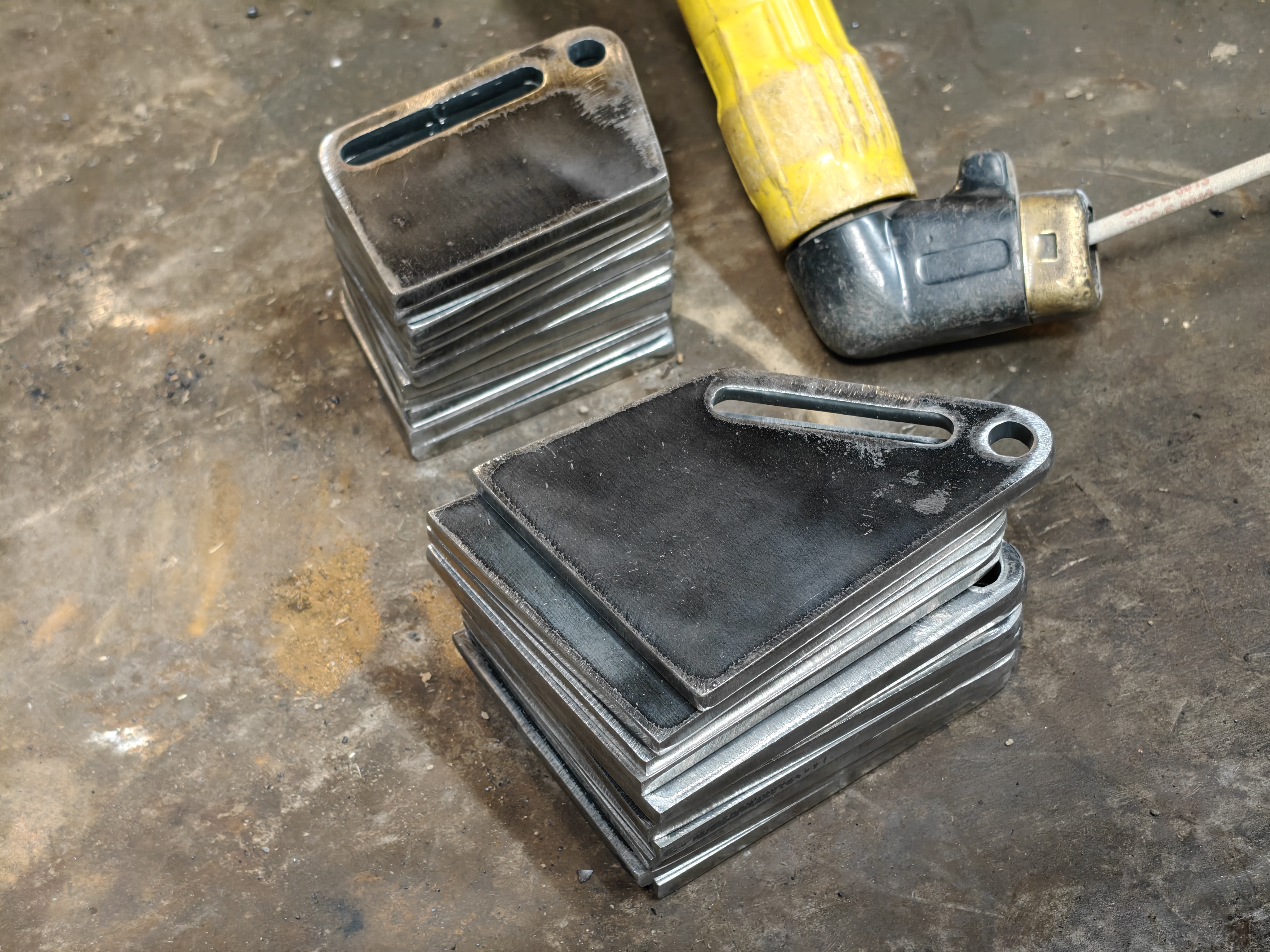
On our farm, we've got a hand-held plasma cutter, which is perfectly good for plenty of jobs. However, when we needed a batch of brackets for a rape drill adaptor, it made more sense to get them professionally cut rather than measuring, marking and cutting every one by hand.
You don't necessarily need to go to a large engineering company either. There are British companies such as SendCutBend, based in West Yorkshire, and Design Make Send, both of which manufacture parts here in the UK. Alternatively, you might even have a neighbour with a CNC plasma table.
For a simple one-off part, cutting it yourself might still be cheaper, especially once you account for delivery and minimum order charges. But for complicated shapes or a batch of identical parts, CNC cutting is well worth considering.
Another advantage is that once you've got the DXF, you can use it again. If you need another ten brackets in a year's time, there's no need to measure and draw everything out from scratch.
What does the process look like?
1. Getting the shape and measurements
Before we can make a DXF, we need to work out what you want made. This could be a completely new design, a modification to an existing part or a replacement for something that's broken.
There are several ways of going about this, and you don't necessarily need any fancy equipment.
A sketch and some measurements
For straightforward parts, a rough sketch with a few measurements may be all that's needed. Things like the overall size, hole positions and slot widths are the important bits.
If you're designing something new, it also helps to know what it needs to fit onto or around. A few photos and measurements of the machine can save a lot of guesswork.
Using a photograph
For more complicated shapes, a photograph can be a useful starting point. Ideally, take the picture square-on to the part and stand back a little to reduce perspective distortion.
Put a ruler or something of known size in the picture so we can scale it in CAD. It's a useful way to recreate an outline, although important dimensions should still be measured rather than relying entirely on the photograph.
Using a scanner
If you've got a flat part or a cardboard or plywood template, an ordinary printer scanner can work surprisingly well. Simply place it on the scanner bed with a ruler alongside it.
This is particularly useful for irregular shapes that would be difficult to measure by hand. Just make sure the scan hasn't been resized before using it in CAD.
There are other methods, including photogrammetry and 3D scanning, but we'll cover those in more detail in our upcoming Cheapskate's Guide to Reverse Engineering.
2. Drawing it in CAD
Once we've got a sketch, measurements or a scanned template, the next step is to turn it into a CAD drawing.
For something simple, like a flat mounting plate, this might just mean drawing the outside shape and adding the holes and slots. For more complicated parts, particularly those that need folding or fitting around other components, it can be easier to make a 3D model first.
Two good examples are the Horsch covering tine bracket and a JCB telehandler bucket.
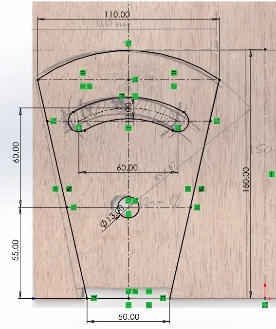
For the Horsch bracket, I imported the scan of the plywood template into CAD and used it as a guide to draw the outline. From there, I could check the important dimensions and hole positions before preparing the DXF.
The Horsch bracket took around 20 minutes to draw in CAD, so it doesn't necessarily have to be a lengthy process.
The JCB bucket is another interesting example. By taking a photograph from the side, I could trace the more complicated external shape without having to measure every curve individually.
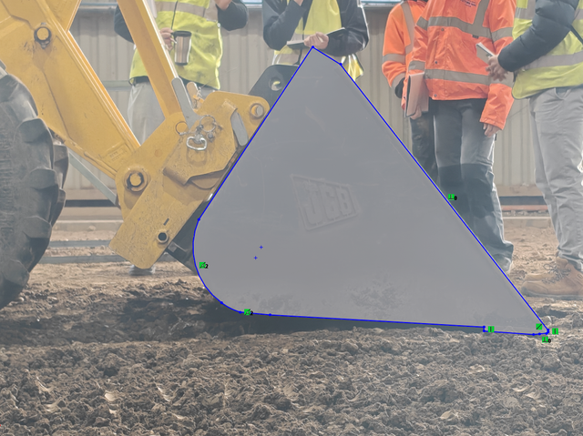
Of course, a photograph isn't a substitute for accurate measurements. We still need to check things like hole centres, overall dimensions and anything that needs to fit another component.
Once we're happy with the design, we're ready to prepare the DXF for cutting.
3. Preparing the DXF
Once we're happy with the design, it's time to prepare the DXF file ready for cutting.
For a simple flat bracket, this is fairly straightforward. We export the outside shape, holes and slots as a 2D drawing. If the part has folds, CAD software can usually unfold the 3D model to create a flat pattern ready for cutting and bending.
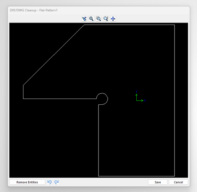
Before sending it off, there are a few things worth checking:
- Scale: The drawing should be full size (1:1), normally in millimetres.
- Cutting lines: Make sure there are no unwanted gaps, overlapping lines or stray bits of geometry.
- Holes and slots: Check their sizes and positions, particularly where bolts or other components need to fit.
- Bend lines: If the part needs folding, these must be clearly distinguished from the cutting lines.
One thing to remember is that the DXF doesn't normally contain all the information needed to manufacture the part. You'll also need to tell the cutting company what material and thickness you want, how many parts you need and whether any bending is required.
Most online cutting services let you upload the DXF directly to their website, where you can check the shape and get a price before ordering.
If you're unsure about anything, it's worth checking with the cutting company before placing the order. It's considerably easier to correct a drawing than a stack of incorrectly cut steel!
4. Having it cut
Once you've got a suitable DXF, you're not tied to us or any particular cutting company. You can send it to a local fabricator, an online cutting service or even a neighbour with a CNC plasma table.
There are several ways to get steel cut, depending on what you're making:
- Plasma cutting: A common option for steel plate, particularly thicker material where a very fine finish isn't essential.
- Laser cutting: Generally better suited to finer details, smaller holes and parts that need a cleaner, more accurate cut.
- Waterjet cutting: Uses high-pressure water mixed with an abrasive to cut through material without heating it. Useful for materials or components where heat could cause problems.
For most everyday farm brackets and mounting plates, plasma or laser cutting will do the job perfectly well.
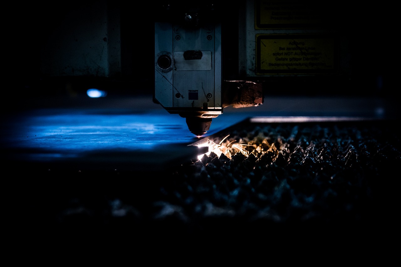
Before ordering, double-check the dimensions, material thickness and quantity. If you're using an online service, most will show you a preview of the part before you confirm the order.
Once the parts arrive, all that's left is to check they fit and get on with the fabrication.
And if you've saved the DXF somewhere sensible, getting another batch made in the future should be as simple as sending the same file off again.
What if you don't have CAD software?
Don't worry if you've never used CAD before. As we've covered, you don't necessarily need much more than a rough sketch, a few measurements or some photographs to get started.
If you fancy having a go yourself, there are free CAD programmes available that can produce DXF files. For simple brackets and plates, you don't need to be an expert to get something useful out of them.
Alternatively, if you'd rather leave the computer work to somebody else, that's exactly the sort of thing we do at 3volveD.
Whether it's a replacement bracket, a modification to an existing machine or something completely new, we can help turn your ideas and measurements into drawings ready for manufacture.
Glossary
- CAD (Computer-Aided Design)
- Software used to create accurate 2D drawings and 3D models of parts and assemblies.
- CNC (Computer Numerical Control)
- A way of controlling machinery using a computer programme. In this guide, we're mainly talking about machines that automatically cut shapes from sheet metal.
- DXF (Drawing Exchange Format)
- A common file format used to share CAD drawings between different programmes. For CNC cutting, it normally contains the 2D outlines of the parts you want made.
- Flat Pattern
- The unfolded shape of a sheet metal component before it's bent into its finished form.
- Bend Lines
- Lines on a drawing showing where a sheet metal part needs to be folded. These need to be distinguished from the lines that tell the machine where to cut.